
Onan CMM - 7,000 Watt
Inverter controlled starting
 |
Location of terminals for generator control - This is the left side of the inverter. As mounted in the truck, this end of the unit is difficult to view. |
|
|
Detail of relay terminals - The "Y" shape in the center of each relay indicates the center, or active, contact as the vertical leg; the solid line to the left is the normally closed path; the dotted leg, to the left, is the normally open path. |
Remote Start Switch
 |
Remote generator start. This is the wiring diagram for the remote start and meter assembly. It is located in the attic control panel |
The function of the start/stop switch is to connect ground, -12 vdc, to either the start terminal or the stop terminal. The switch is a two position rocker with an integrated LED indicator. The switch is connected, in parallel, with a similar switch built in to the generator. The same functions, start/stop, are provided by the inverter, and isolation relays, by providing the ground signal to the appropriate terminals. Again, this connection is in parallel, and made at the rear of the remote start switch in the attic control panel with wires run from the rear compartment.
Details of the connections from the inverter to the isolation relays are available here.
| Exterior - Closed | |
| Exterior - Open | |
| Extended | |
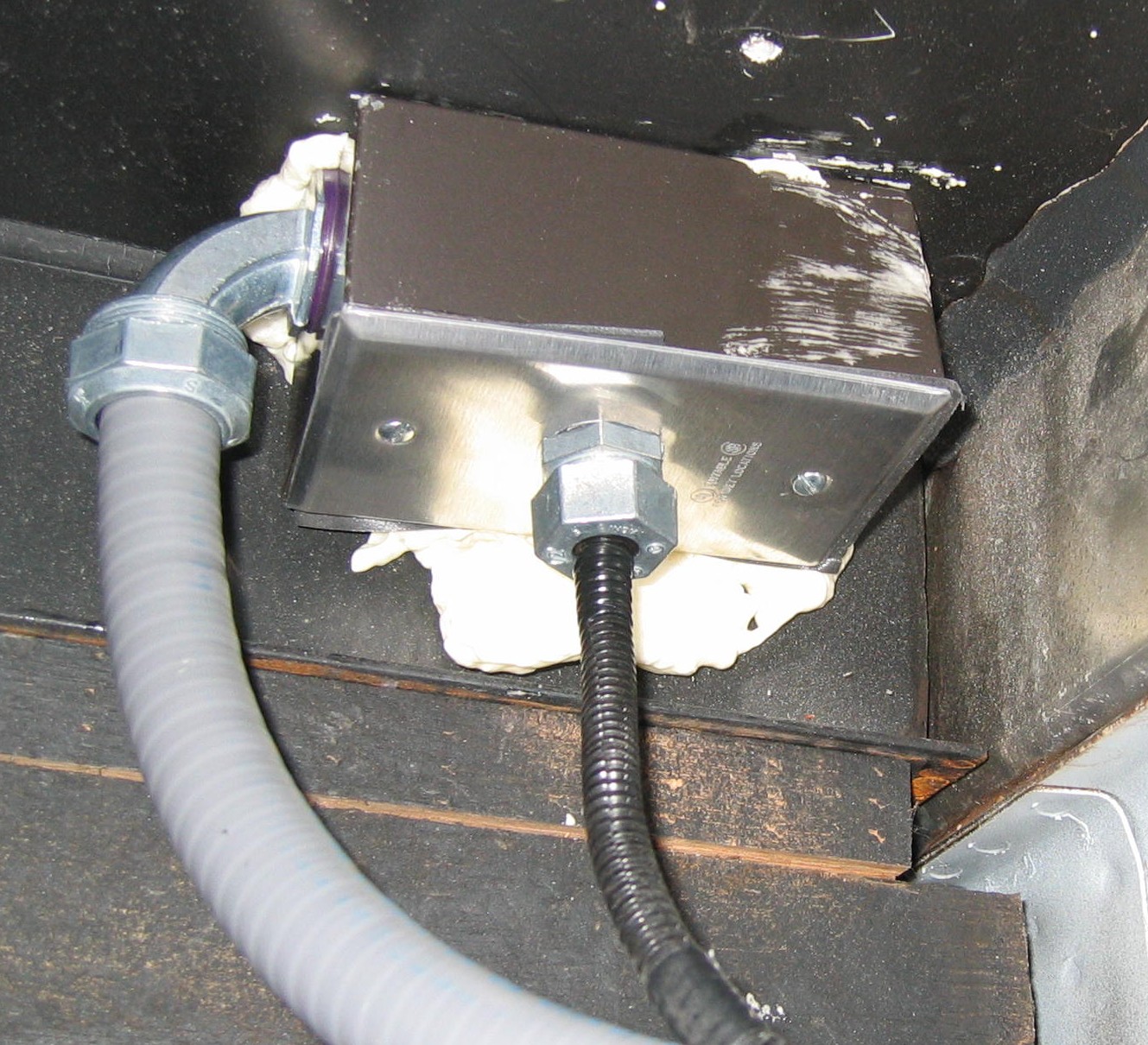 |
Curb-side under-floor junction |
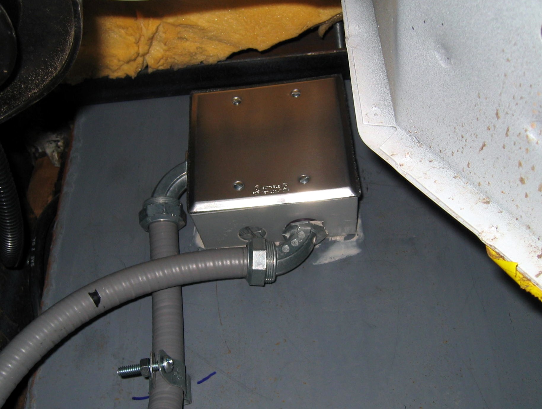 |
Junction on front of generator compartment. |